This board was created in the Fall 2024 offering of HOPE with my awesome group partners, Kimberly and Mallika. It is the heart of a smart home device that sits on your nightstand or your desk, and can either manually or automatically control your other home devices while telling you information about your environment all through a simple, user-friendly interface. We thought that this would be a great addition to our own homes, while giving us solid experience on hardware and firmware development for devices related to IoT.
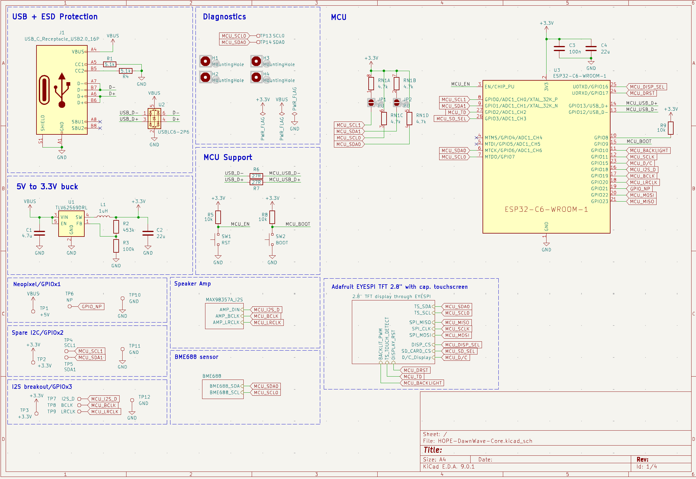
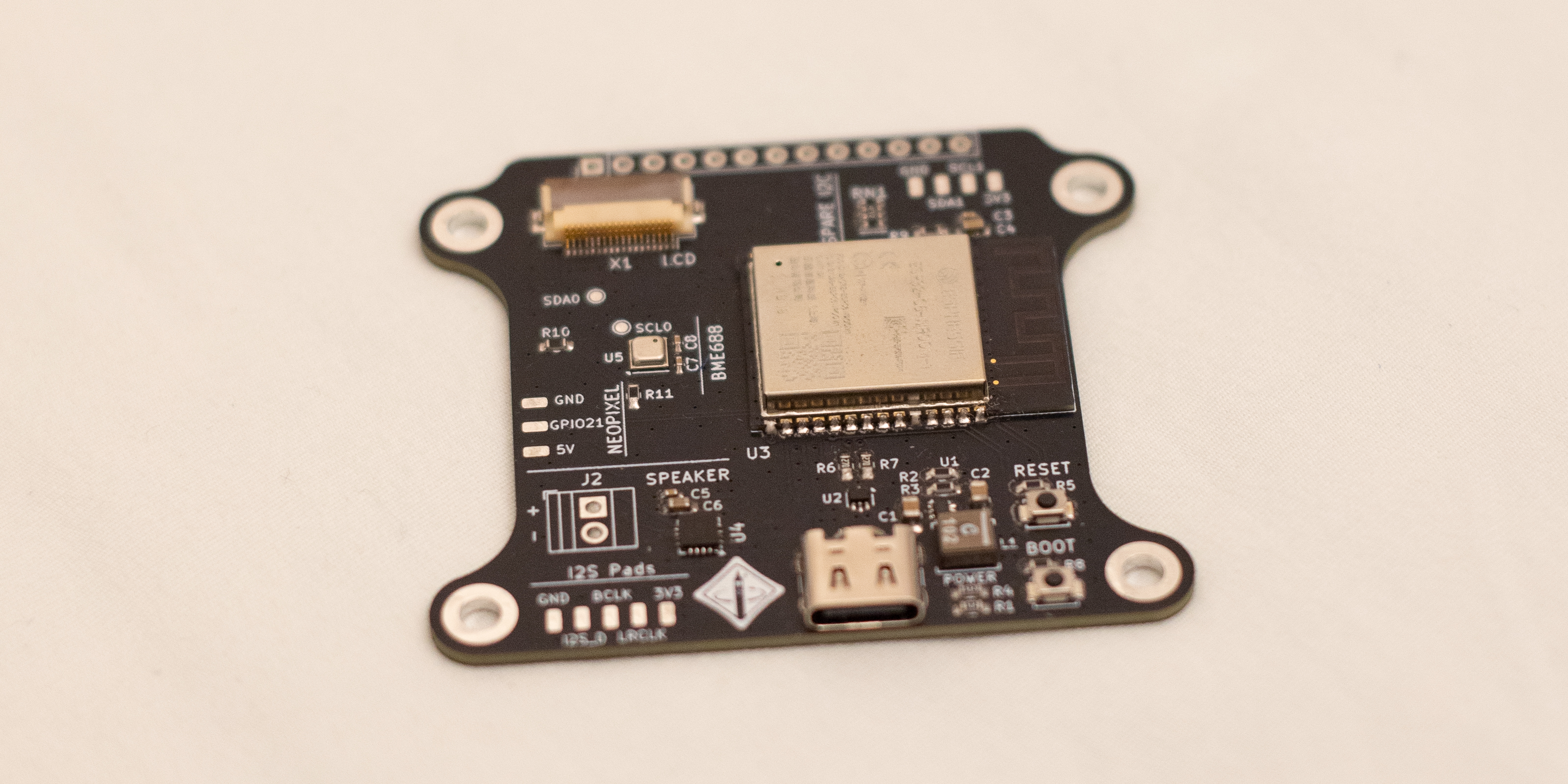
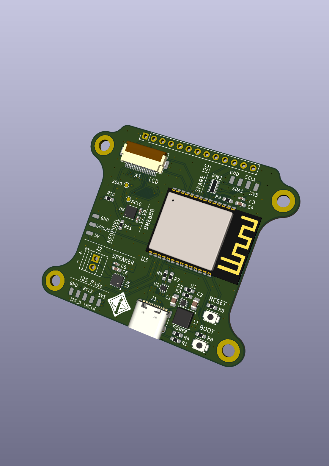
Dual-core RISC-V SoC with WiFi 6 and BLE 5. We chose this system because it was specifically advertised to support Matter and Zigbee, which we hoped to integrate DawnWave with. Although its IO counts are limited compared to some other ESP32 offerings, on paper it has some of the best wireless communication features of them all, and it is quite easy to work with in terms of wiring and firmware.
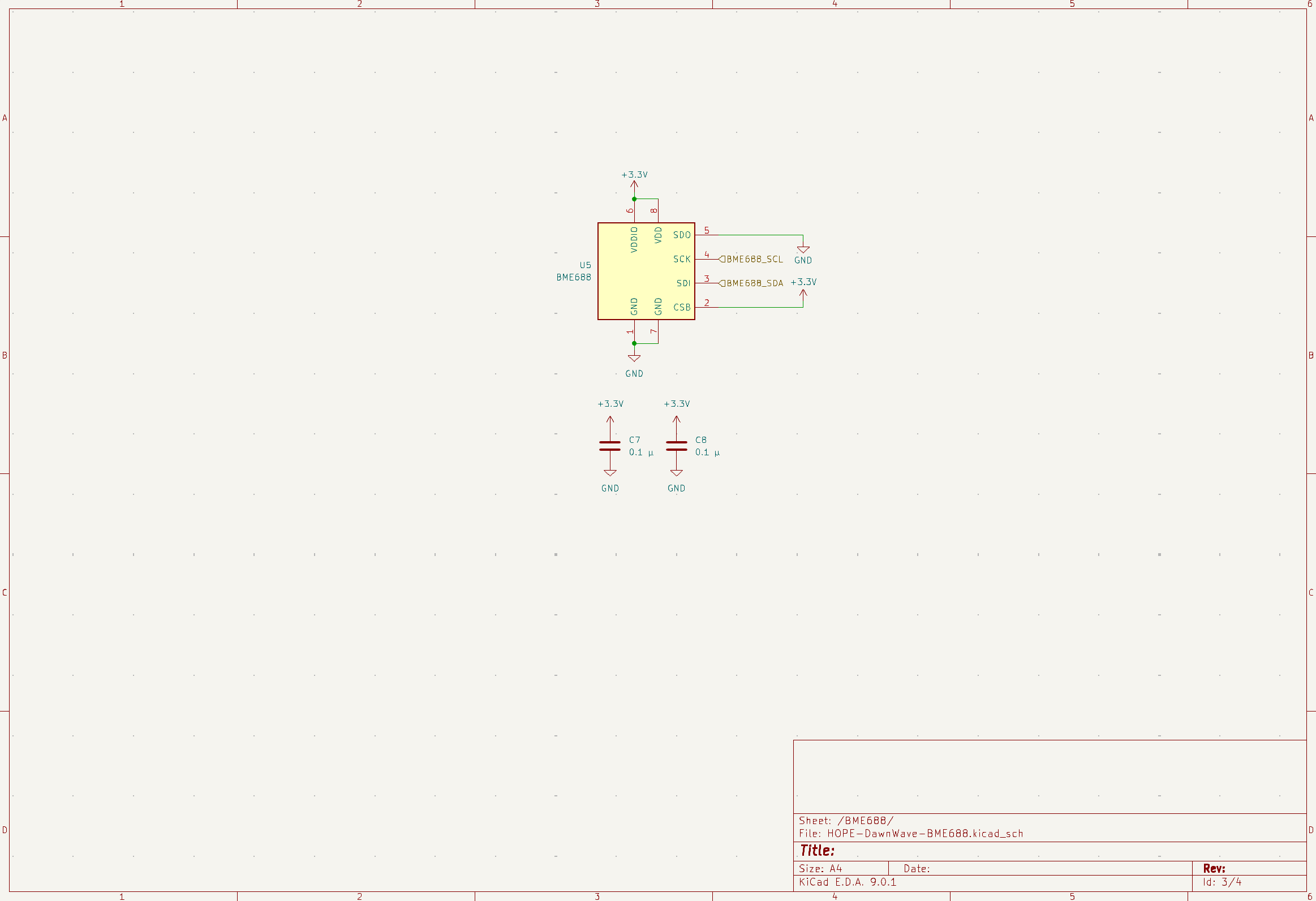
This sensor provides temperature, humidity, pressure, and VOC data over I2C or SPI in a surprisingly small package. We chose it because of its compact size and low required component count (just two capacitors), which would be much easier to work with if we decided to make the board smaller in the future. It also has great firmware library support, which was very helpful due to time constraints.
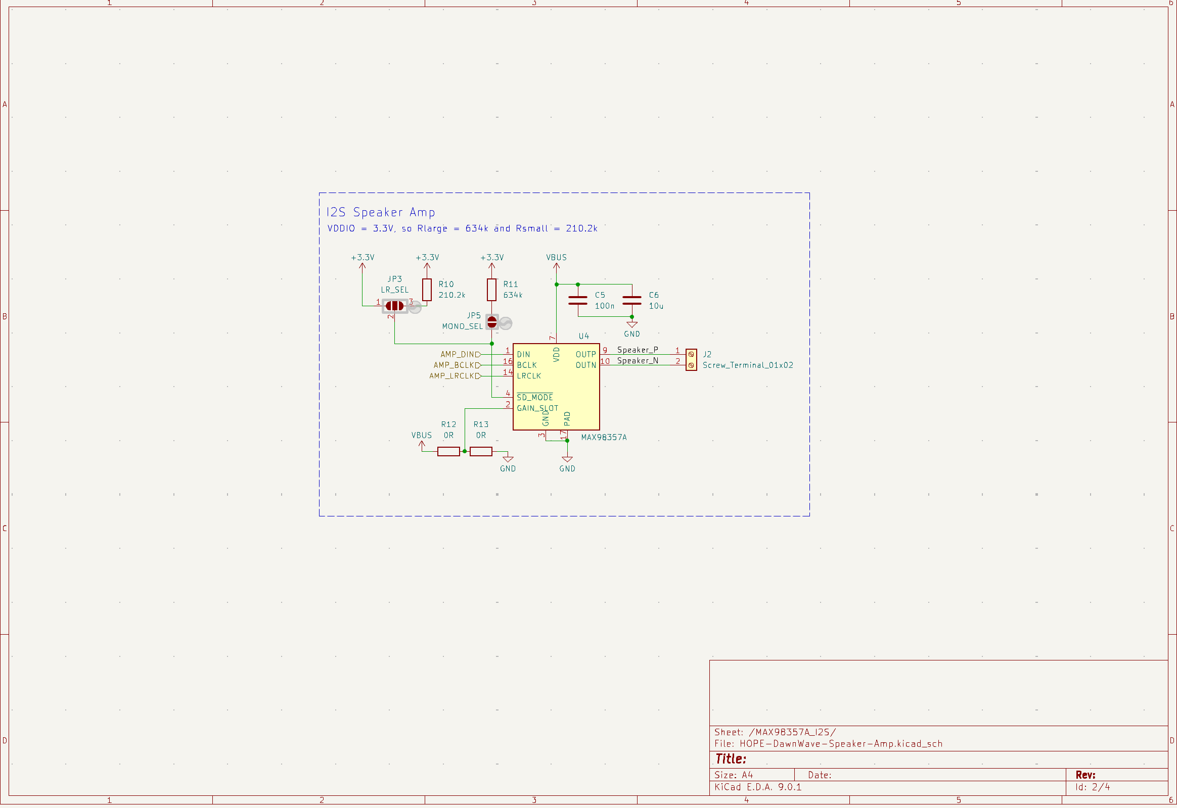
An I2S speaker amplifier with simple configuration options. This is used for the alarm clock functionality of the board, and with the microSD card in the display, it allows users to choose anything they want for their alarm sounds.
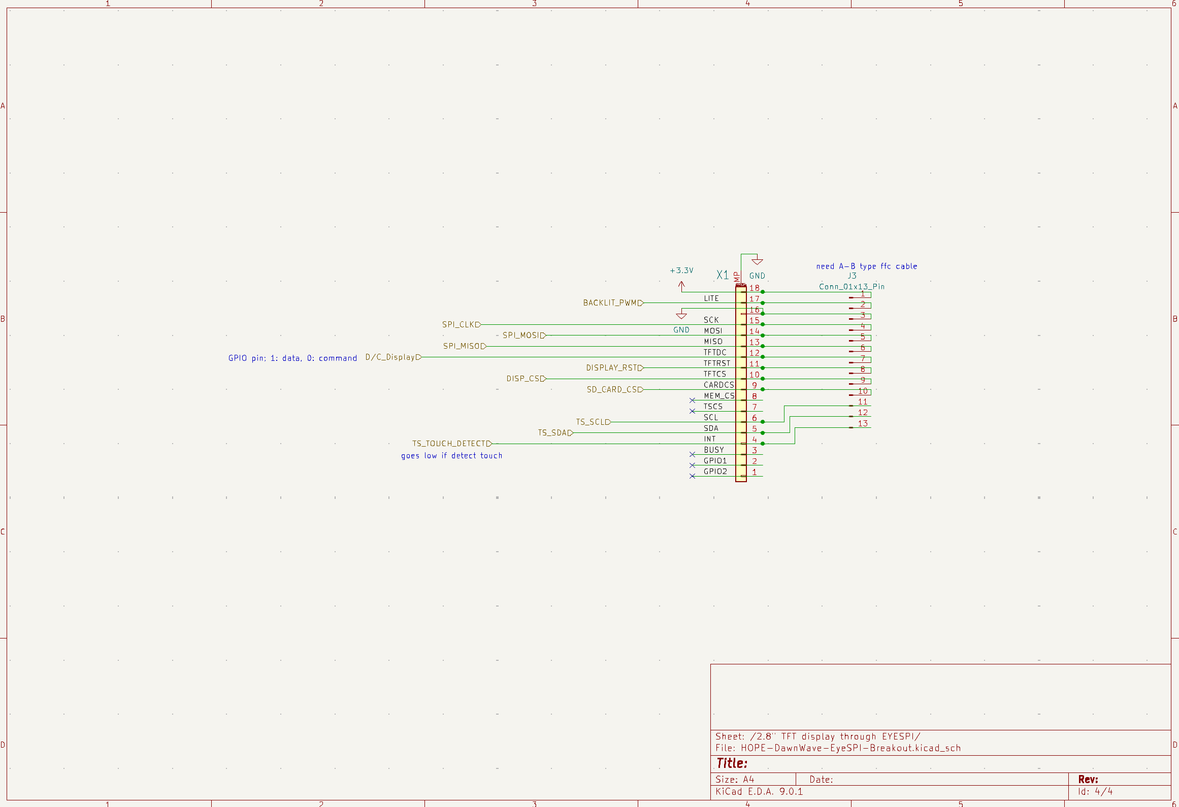
The interface users interact with. The touchscreen interfaces with this board following the Adafruit EYESPI 18-pin FPC cable pinout. The cable allows access to the touchscreen driver over I2C and both the microSD card and display driver over SPI.
We chose to include these spare solder pads in the event that we wanted to add extra sensors or functionality to the board. An I2S microphone can be wired from a more optimal location for voice or sound recognition, and any other external I2C peripheral can be added on a dedicated bus separate from the one used on the board.
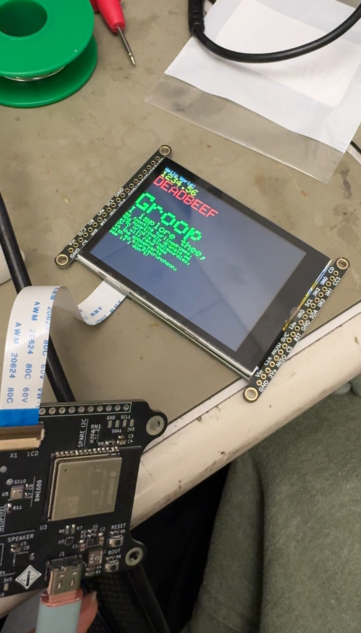
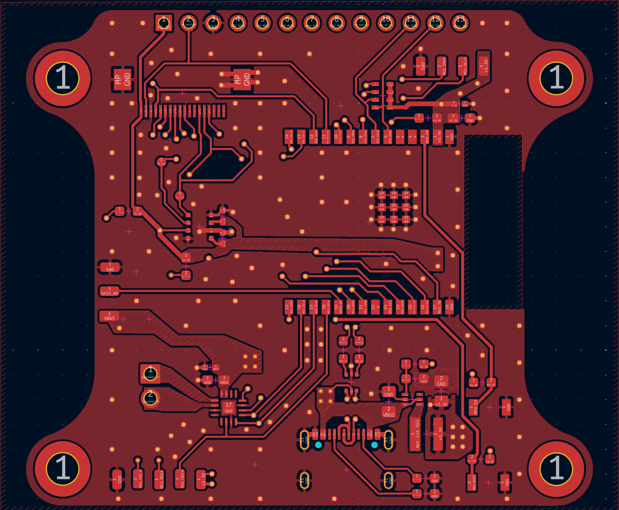
We assembled this board by hand with the help of a stencil and a reflow oven. We ended up adding too much solder paste to the board, so manual rework was necessary. Besides that, everything functioned as expected! The devices that are currently in use in firmware are the BME688 and touchscreen driver on I2C 0, and the display on SPI.
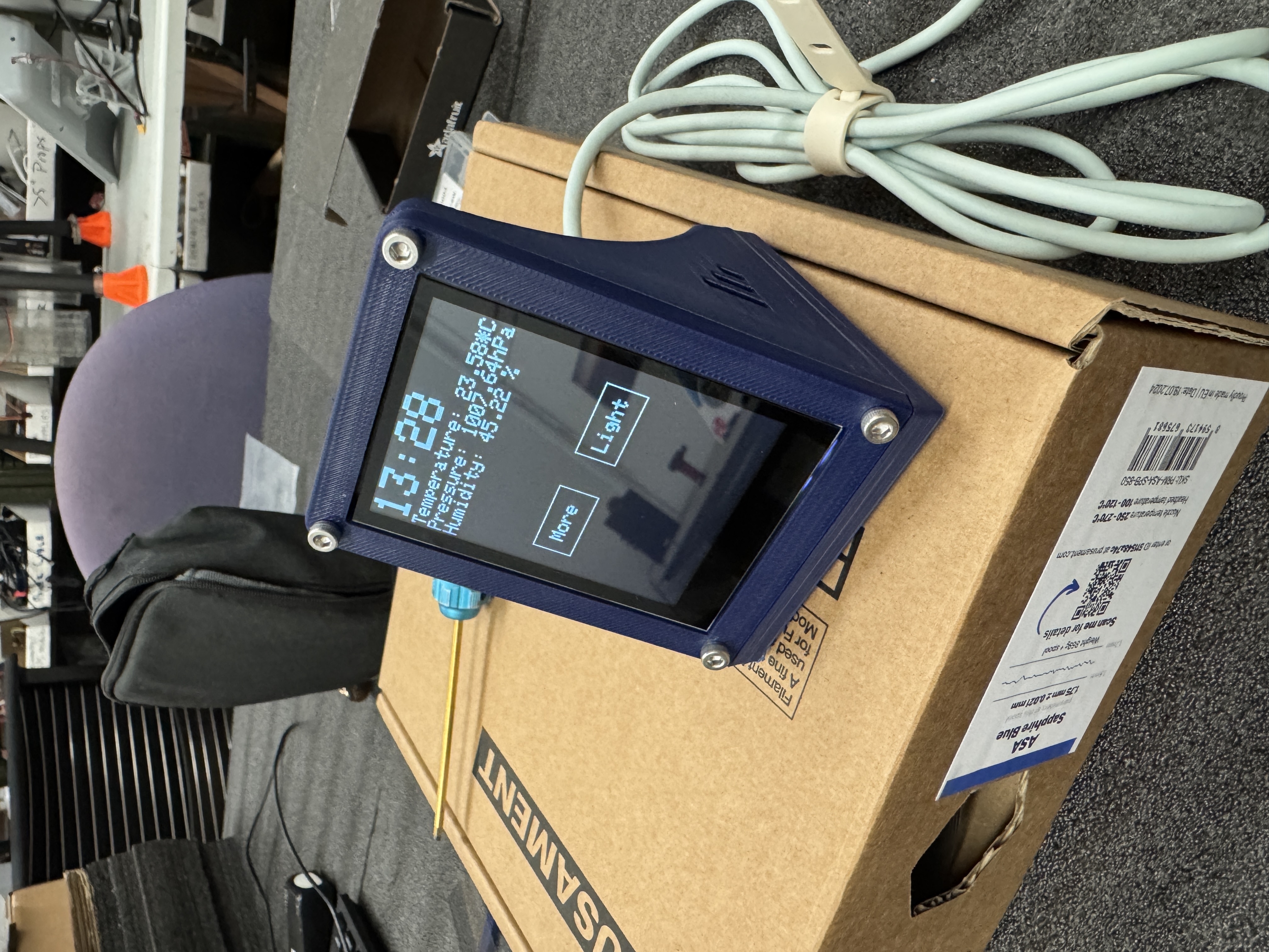
At the end of the semester, we were able to implement several of our initial goals in firmware. Our final functionality included internet connectivity to obtain accurate time, readout of all four data streams from the BME688 (temperature, humidity, air pressure, and VOC concentration), and a display of all this data in an easy-to-read format on the LCD screen. We also included a test interface of what a controllable light switch would look like on our device.
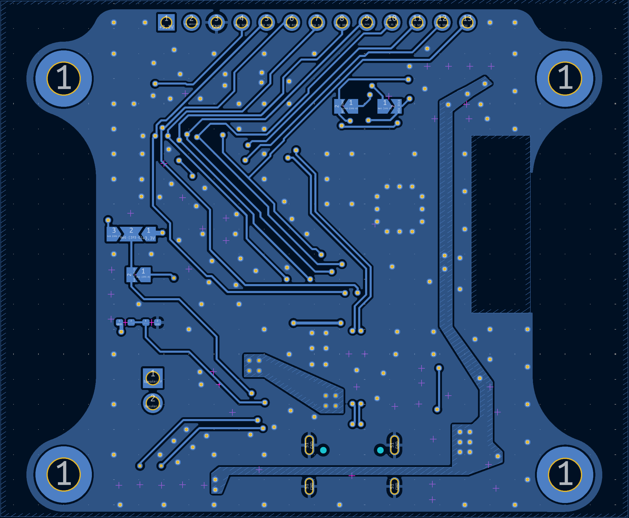
In order to further decrease the footprint of this board, we will redesign this board to use a much denser two-sided layout. The 2.54mm header pins at the top of the board will also be removed, because they were added for debugging purposes. Something that we noticed was that the display refresh rate was rather slow, so we may consider using its 8-bit data bus instead.