Part of the RoboNation SUAS competition requires the safe delivery of a payload as close to a target as possible. Our team settled on a parachute drop system to minimize the time needed to deliver a payload, but the altitude of that drop meant that wind could significantly affect accuracy. To solve this problem, I decided that delaying the opening of the parachute would reduce drift enough for the competition task. As of the creation of this PCB, there wasn't a product on the market that satisfied our needs and constraints. Because of this, I thought that it would be a great opportunity to learn PCB design and see if I would enjoy it. It's safe to say that I did!
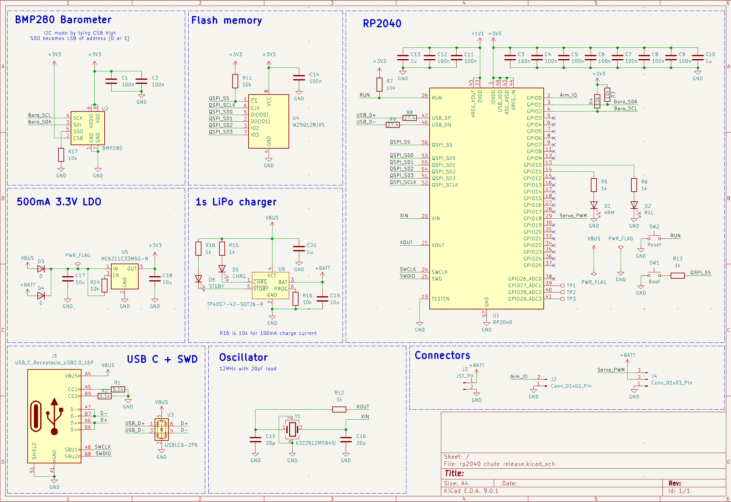
Dual-core ARM processor created by Raspberry Pi. I selected it because it is one of the most forgiving MCUs to layout, and easily programmable through a variety of workflows.
Air pressure sensor operating in I2C mode. This allows the board to determine what height it is at in order to open the parachute. The readings can sometimes be noisy, which is why a backup timer is used in the firmware to ensure deployment.
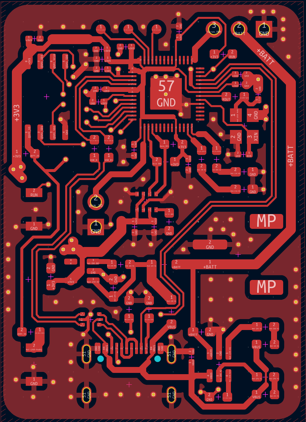
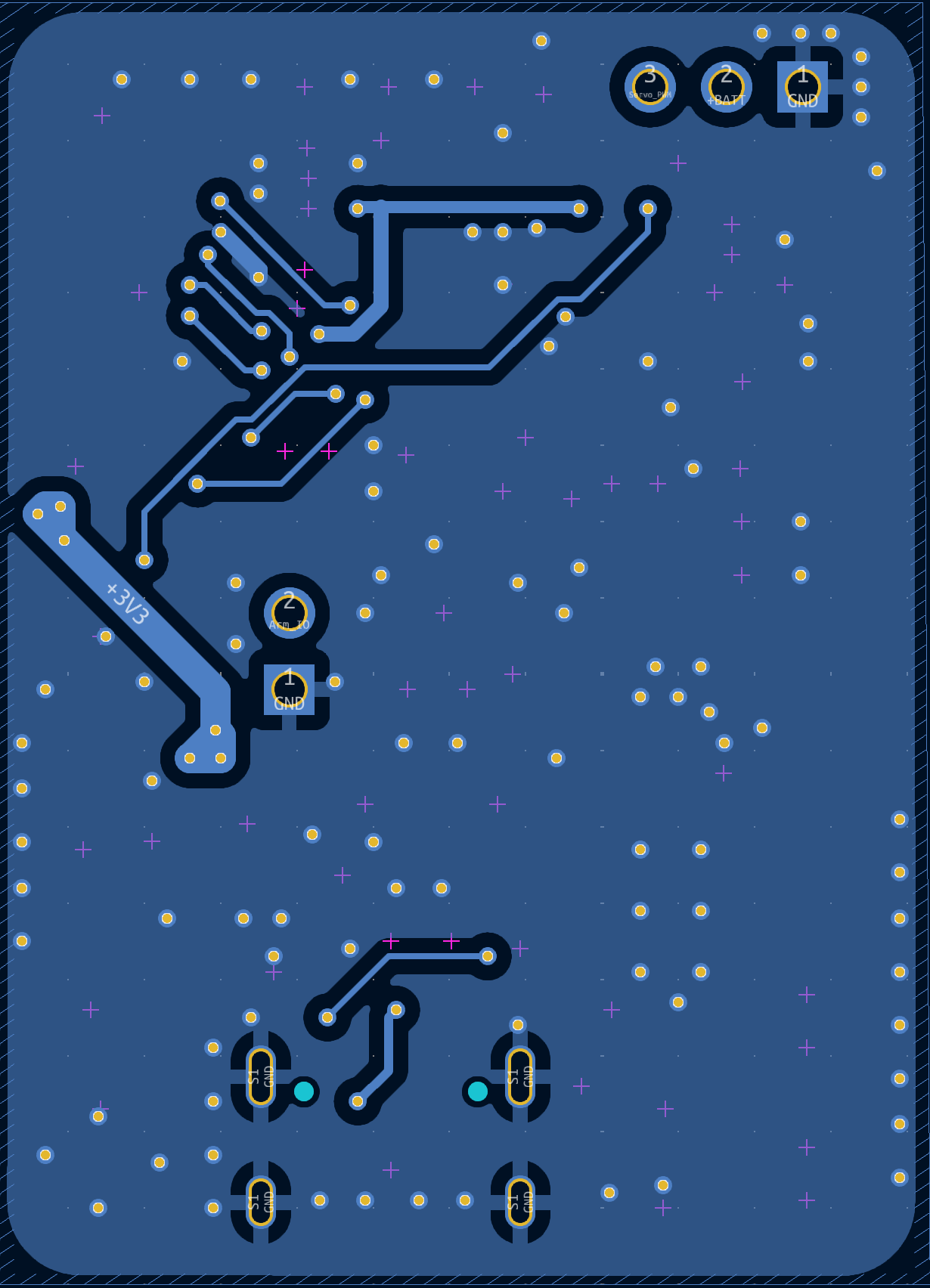
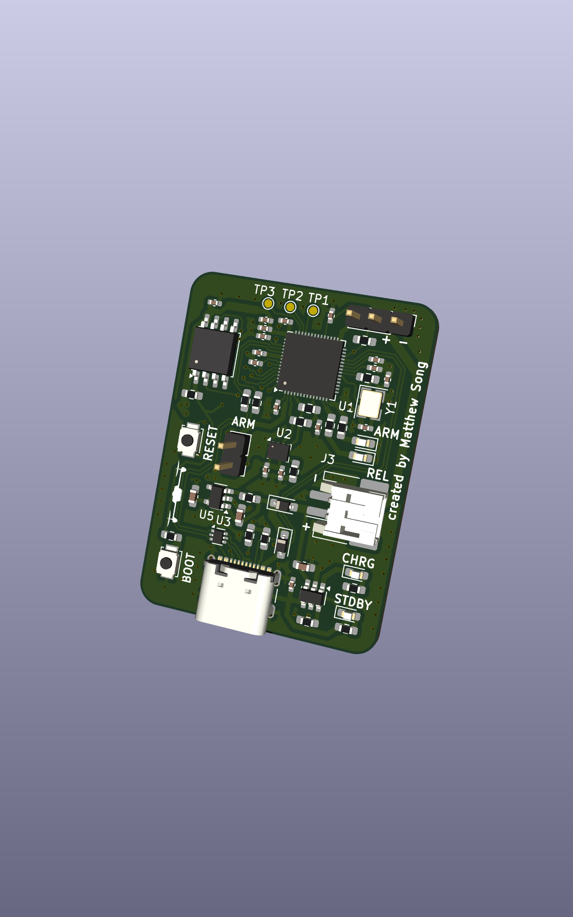
This board uses components almost exclusively from JLCPCB's Basic Parts catalog. I wanted to see how low I could get the cost of this board because it was my first attempt at PCB design, and they would need to undergo extensive acceptance testing for our payload system. Those parts were used along with single-sided assembly, two layers, and easily manufacturable via sizes. This yielded a cost of less than $15 per board including assembly fees.
This particular wiring scheme was inspired by Anton Khrustalev's project, an enhanced version of the ST-Link programmer. The often unused SBU1 and SBU2 pins on the USB-C connector are repurposed as the SWCLK and SDIO lines for SWD. I decided to include SWD in the event that something went catastrophically wrong with my layout.
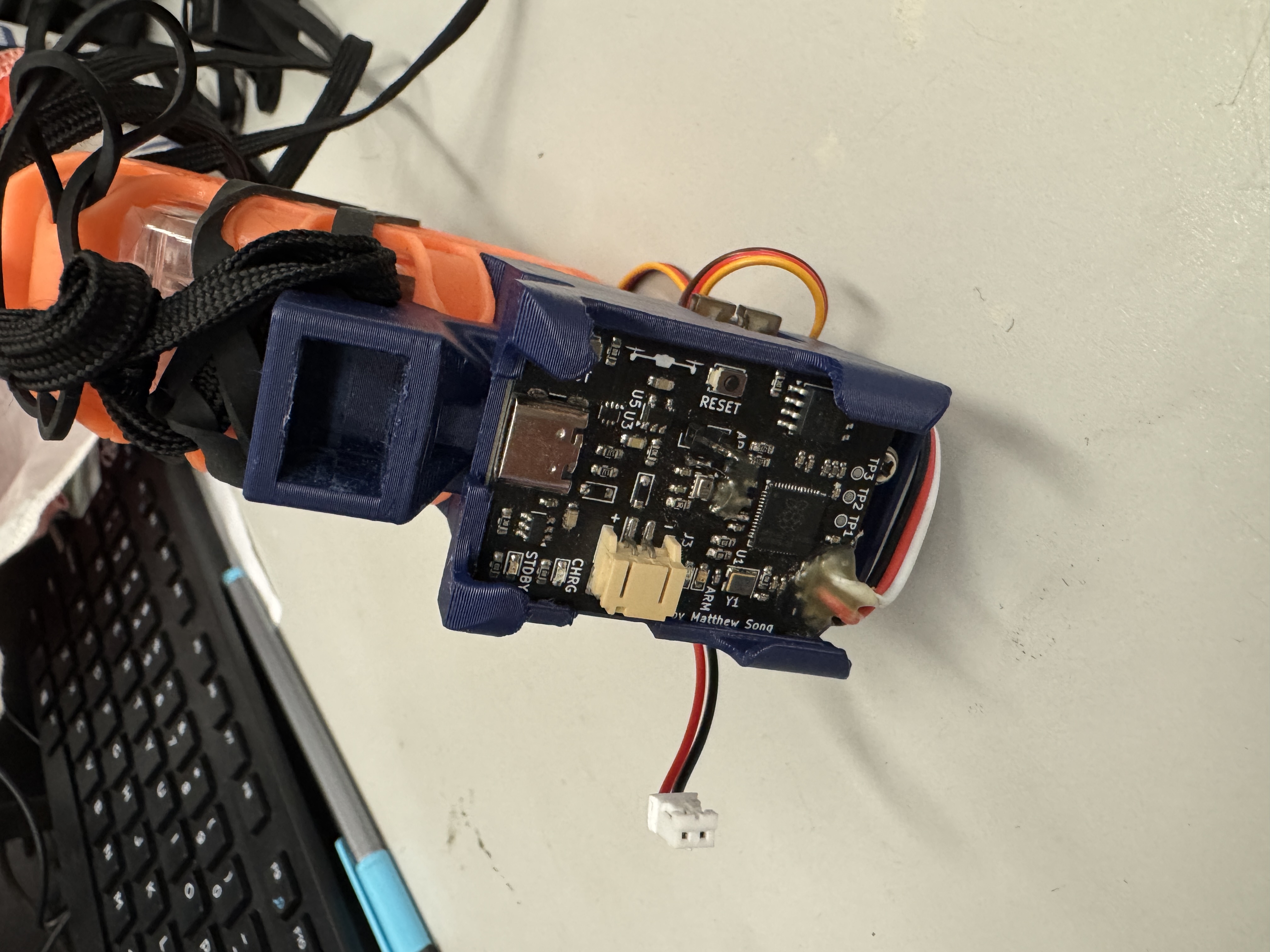
All components are on one side of the board. This was because I wanted more flexibility to mount the board to any style of payload, while keeping assembly costs low. I would also be able to easily rework components if necessary.
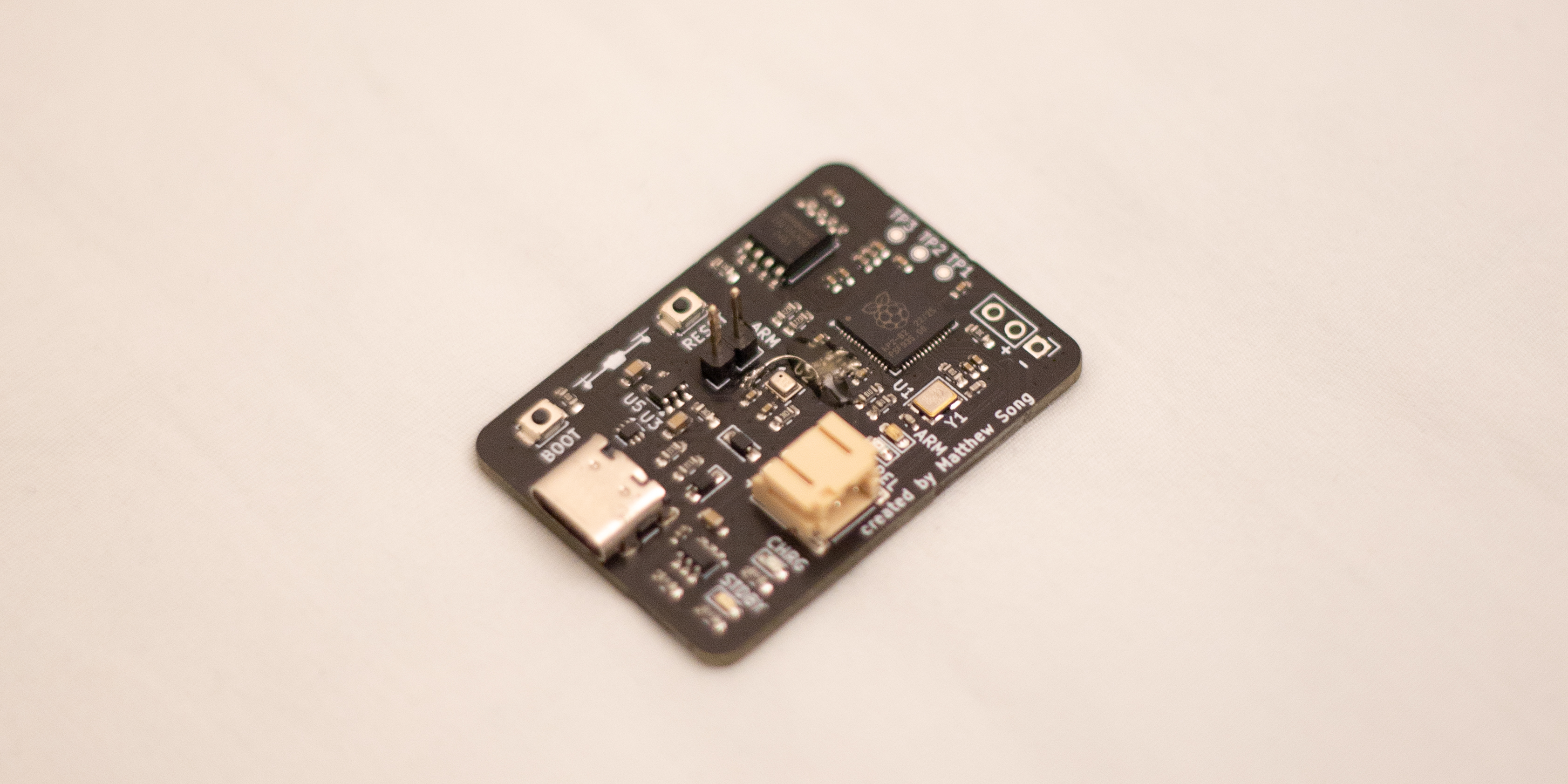
The I2C bus between the RP2040 and the BMP280 were the only sources of trouble for this board. I had forgotten the pullup resistors on it, so I hand-soldered pullups to a nearby 3V3 pad. The next issue was firmware related. I had selected the wrong pads to use for hardware I2C on the RP2040, so the Arduino IDE was impossible to use with it, even after attempting to recompile the libraries with software I2C support. In the end, I used MicroPython to successfully program the board.
The board has been fully integrated into our payload system, and drop tests have been conducted succesfully! We will continue characterizing the behavior of the onboard barometer before we bring it to competition.
The drop signal from the flight controller on the drone is at 5V logic level, while the input on the board is only 3.3V tolerant. Currently, I am using an external resistive divider for level shifting, but adding it to the board will be quite simple. To further reduce the weight and footprint of the board, and improve its impact resistance, I plan to add proper mounting holes and make the board double-sided with smaller components.